 |
|
..:: SAAB FAQ :: 900 Old Generation :: Бентли :: Часть 1 ::..The APC system consists of simple electronics. A knock sensor on the engine block senses the onset and degree of engine knock and transmits an electrical signal to the control unit. The control unit also receives signals from the intake manifold pressure sensor and the ignition system (engine rpm). The data is processed by the control unit, which transmits a signal to the APC solenoid valve to regulate the boost pressure (via the wastegate) of the turbocharger. Therefore, maximum operating boost pressure under full engine load is electronically governed. In the event of an APC system malfunction,the wastegate is mechanically adjusted to provide a safe, low boost pressure limit. Fuel Injection All Saab 900 16-valve models use an electronically controlled Bosch LH-Jetronic fuel injection system. See Fig. 5.
Fig. 5. Schematic of LH-Jetronic fuel injection system used on all Saab 16 valve engines LH is a German acronym for hot wire, or"Luft masse messen mit hitzdraht". Hot wire refers to the operation of the air mass meter, which is used to measure the air entering the engine. The intake air flows across an electrically heated platinum wire in the tubular air meter. See Fig.6.
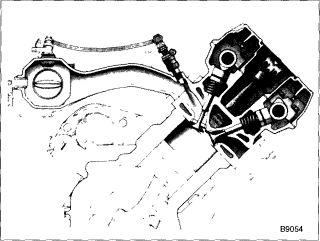
Fig. 6. View of LH (hot wire) air mass meter. The platinum heated wire is maintained at a constant temperature and measures the mass of the air flow going into the engine. It uses solid-state circuitry and has no moving parts to wear out. The inset shows a front view of air massmeter. The control unit then measures the electrical energy necessary to maintainthe wire at a constant temperature as a measure of the air mass. At the same time the control unit senses the engine speed and the engine temperature, which enables it to meter the correct quantity of fuel to suit the requirements of the engine at all times. Fuel is delivered to the engine through the fuel injectors. The intake manifold is equipped with one fuel injector per cylinder. Each injector is fitted upstream of the corresponding intake valves and actuated electro-magnetically by signals from the electronic control unit. The control unit calculates the opening time for the injectors so that the quantity of the fuel injected will be correct in relation to the quantity of air flowing to the engine. See Fig.7.
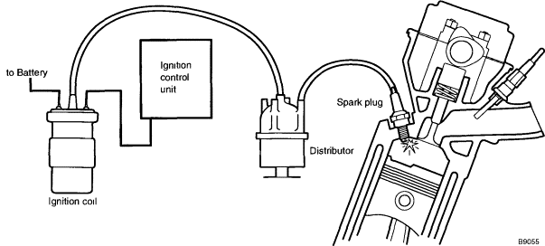
Fig. 7. Cutaway view of engine showing operation of the electromagnetic fuel injector. The injectors are mounted in the intake manifold, one for each cylinder. Ignition System The electronic ignition system creates the high-voltage spark necessary to ignite the combustible air/fuel mixture in the cylinders. The ignition coil boosts the voltage so that the spark will be hot enough to ignite the air/fuel mixture.The timing of the spark is controlled by the ignition control unit. The ignition distributor, synchronized to the rotation of the engine, delivers the spark to the right cylinder at precisely right time. Since each cylinder has to have a spark once for every two revolutions of the crankshaft, the distributor turns at one-half crankshaftspeed. The basic system is shown schematically in Fig. 8.
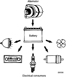
Fig. 8. Schematic of typical ignition system Electrical System Many components, and all electrical accessories, are powered by the car's electrical system. The electrical system uses a battery to store energy, an engine-driven alternator to generate electricity and recharge the battery, and various wiring harnesses and other circuits to distribute electric power to the rest of the car. The electrical system is represented in Fig. 9.
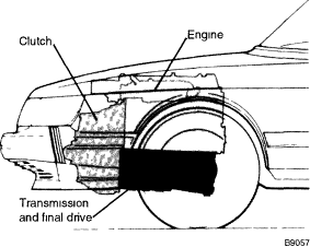
Fig. 9. The alternator generates electricity to recharge battery and power other electrical consumers The flow of electricity depends upon a closed-loop path — a complete circuit. Electrical current flows through wires to the consumer, a light bulb for example, and back to the battery in a complete circuit. The electrical route back to the source, which completes the circuit, is called a path to ground. Every consumer of electrical power in the car must have a source of power and a path to ground in order to operate. Commonly, the electrically conductive metal structure of the automobile is used as a ground path. The negative (-) terminal of the battery connects to the car body, and all of the electrical consumers in the car make a ground connection to the car body, thus eliminating the need for many feet of additional wire. Electrical components near the engine are often grounded directly to the engine, which is then grounded to the body. Some components are grounded through their housings which are bolted to a ground. Electrically, the effect is the same. Transmission and Drive Train The transmission is mounted beneath the engine and is arranged in a housing together with the final drive. See Fig. 10.
Fig. 10. The transmission and final drive are mounted beneath engine The transmission is chaindriven off the engine via the clutch. Although the Saab engine develops a substantial amount of power, it does so best at relatively high revolutions per minute (rpm). To handle all driving conditions,it is necessary to use gearing to change the ratio of engine rpm to vehicle speed. See Fig. 11.
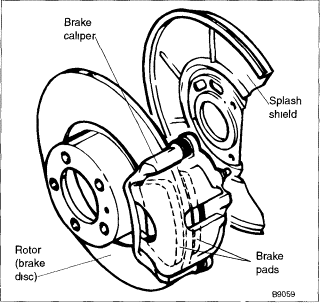
Fig. 11. The gear reduction between the engine and the driven wheels takes place in three stages the primary chain drive the transmission gears and the final drive A manual transmission arranges several sets of gears in a common housing. A set of two gears determines a gear ratio, each suited to a particular range of driving speeds. A shifting mechanism allows the driver to change from one gear ratio to the next to match vehicle speed. In an automatic transmission, hydraulic fluid under pressure in a complex network of passages,valves and control mechanisms engage and disengage constantly meshed planetary gear sets. Hydraulic controls responding to vehicle speed, engine load, throttle position and gear shift position select the appropriate gear ratio. Brakes All of the Saab models covered in this manual feature disc brakes at all four wheels. A disc brake squeezes pads lined with friction material against both sides of a flat, round brake disc, called a rotor. A typical disc brake assembly is shown in Fig 12
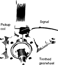
Fig. 12 Disc brake assembly showing disc caliper and splash shield Caliper assembly holds pads with friction material The brakes act to slow or stop the car by causing friction. Since cars are relatively heavy, the friction required to stop safely and effectively is quite high, and generating this friction requires considerable force. The cars covered by this manual use either an engine vacuum boost system or hydraulic boost system (cars with ABS) to multiply the force applied to the brake pedal and to distribute it uniformly to the wheels The brake pedal is connected by a mechanical linkage to the master cylinder, mounted on the firewall at the back of the engine compartment. A piston in the master cylinder creates hydraulic pressure in the brake lines going to the wheels At each wheel, the hydraulic pressure acts on the brake caliper to cause friction and slow the wheel. The sizes of the hydraulic components are such that the driver's force applied to the brake pedal is multiplied many times by the time it reaches the wheels 1990 and later 900 models are equipped with an anti-lock braking system (ABS). As the name implies, the purpose of this system is to prevent the wheels from locking during hard braking. Speed sensors at each wheel sense when the wheel is about to lock, and an electronic system modulates the braking force to that wheel See Fig 13
Fig.13 A moisture proof sensor senses the rolling speed of each wheel. The sensor is inductive in that an electric current is induced in the pickup coil every time a tooth on the gearwheel passes the sensor |
| SAABNET.RU | Форум SAABNET.RU |
|
|


